Choosing the right Switch Mode Power Supply starts with more than matching the voltage printed on a device. The load may draw steady current, or surge briefly when motors start and processors wake. That difference matters. A unit rated at 120 watts may still struggle if its peak load, cooling conditions, or input voltage range do not match the application.
Energy use also deserves attention. Lawrence Berkeley National Laboratory’s 2024 United States Data Center Energy Usage Report estimates that U.S. data centers consumed about 176 terawatt-hours of electricity in 2023. That figure describes an entire sector, not an individual power supply, but it shows why conversion losses matter at scale. Uptime Institute’s 2024 Global Data Center Survey reported an average PUE of 1.56, another reminder that power performance depends on the whole system. These reports cannot tell you which model to buy. They do provide useful context.
A practical selection starts with the real operating profile: output voltage, continuous and peak current, ambient temperature, and available airflow. Check efficiency across the loads you actually expect, not only at full output. Review ripple, transient response, protection features, and required safety approvals in the manufacturer’s datasheet. Leave margin. Too much can raise cost and reduce efficiency at light loads; too little can cause instability or premature failure. The label is only a starting point. A careful choice balances electrical fit, thermal behavior, reliability, and service life—and sometimes the datasheet still leaves questions worth asking the supplier.
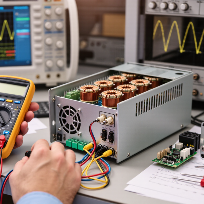
Before comparing switch mode power supplies, define what the application needs at its input and output. Record the available input voltage range, required output voltage, and the load’s normal and peak current. Calculate output power by multiplying voltage by current, and check whether several loads operate at once. A tidy estimate can still miss a short startup surge.
Measure it under load. Motors, relays, and processors may draw brief bursts that exceed their steady-state current. Check the supply’s transient response and ripple limits against the equipment’s needs, especially for sensitive sensors or audio circuits. Also confirm connector polarity and allowable voltage tolerance. Small details matter.
Consider where the supply will operate. A unit inside a warm, closed enclosure may need its output derated, so review the manufacturer’s temperature and cooling data. Allow practical headroom, but avoid choosing an oversized supply without a reason. The right margin depends on real load behavior, not a convenient round number. Test a prototype with the actual wiring and load; estimates sometimes need revision.
Before choosing a switch mode power supply, compare its input range with the actual source. A unit rated for 100–240 V AC may suit a wide range of mains supplies, but check frequency and any low-line startup limits. For battery systems, verify the full DC voltage range, including charging peaks and voltage sag. Close counts.
Match the output voltage to the load’s specified operating range, not just its nominal label. A 12 V device may tolerate only a narrow deviation; check the supply’s regulation and ripple figures. Size output current above the load’s continuous draw, then account for startup surges, motors, and simultaneous loads. For example, a 3 A steady load with a 4.5 A startup peak needs a supply whose peak rating and duration cover that surge. Heat matters: allowable output can fall at high ambient temperatures, so inspect derating curves rather than relying on the headline rating. I still recheck connector polarity; it is an easy detail to miss. Lawrence Berkeley National Laboratory’s 2024 U.S. Data Center Energy Usage Report estimates data centers used 176 TWh in 2023, about 4.4% of U.S. electricity. That system-level figure underscores why conversion efficiency deserves attention alongside voltage and current matching.
Choosing a topology starts with the load, not the smallest box on the shelf. A flyback design can suit compact, lower-power equipment with modest output demands. For higher power or tighter efficiency targets, forward or LLC resonant designs may reduce switching losses, but add design and control complexity. Check input-voltage range, isolation needs, transient response, and expected load profile. A topology that looks efficient at full load can perform less well when the device spends most of its time idle. A paper calculation can still mislead.
Form factor is a thermal decision as much as a mechanical one. Measure the available space, then allow room for airflow, connectors, and service access. A sealed enclosure may need a larger power supply or derating to manage heat; a fan-cooled unit needs a clear air path. The IEA’s Electricity 2024 report estimates data-centre electricity use could reach about 1,000 TWh by 2026, underscoring why conversion efficiency and heat deserve attention in power-dense systems. That forecast is not a sizing rule for every product, though. It is context.
Compare candidate units at the actual ambient temperature and load, using their derating curves and efficiency data. Verify mounting, vibration limits, and cooling direction against the finished enclosure. Leave margin, but do not oversize automatically: low-load operation can be less efficient, and the larger unit may complicate thermal layout. I would revisit the choice after a prototype test; airflow often behaves differently than expected.
A switch-mode power supply can look efficient on paper and still run hot inside a crowded enclosure. Compare efficiency across the load range, not just at full output. A unit supplying a small sensor load may spend most of its time far below its rated capacity. Check the manufacturer’s efficiency data at that operating point, and consider the heat the supply must shed. Small details matter.
Protection features should match the equipment and its likely faults. Overcurrent, overvoltage, overtemperature, and short-circuit protection are useful, but their presence alone tells you little about response. Check the product documentation for behavior during a fault and whether the supply recovers automatically. For a motor or other demanding load, startup current can trigger protection unexpectedly. I would verify this with the actual load, since a neat specification sheet cannot reveal every installation wrinkle.
Safety certifications also deserve a close look. Confirm that the exact model—not merely a product family—has the relevant certification for your market and application. Review the stated input range, temperature limits, and installation conditions in its documentation. A certification is meaningful evidence of evaluated safety, but it is not a blanket guarantee of performance in every setup. Don’t skip the fine print.
Compare the minimum efficiency thresholds for 80 PLUS desktop power supply certifications at 20%, 50%, and 100% load (115 V AC). Higher efficiency can reduce wasted energy and heat.
What to check: Choose a supply with sufficient output capacity and efficiency for your expected load. Also verify that its protection features suit your application—commonly overvoltage (OVP), overcurrent (OCP), short-circuit (SCP), and overtemperature (OTP)—and confirm applicable safety approvals for your market and installation. 80 PLUS efficiency ratings alone do not certify these protections or overall product safety.
When choosing a switch mode power supply, start with the conditions around it, not just its rated output. A unit inside a cool, ventilated cabinet faces a different workload from one near a hot motor or dusty workshop floor. Check the full operating-temperature range and whether the manufacturer specifies output derating. At elevated temperatures, available power may fall. Leave room for that reduction.
Moisture, dust, vibration, and altitude can affect service life. A sealed enclosure may limit dust entry, but it can also trap heat. That trade-off is easy to miss. Review the supply’s protection rating, mounting orientation, and cooling requirements against the actual installation. If vibration is expected, secure wiring and connectors; loose connections can cause intermittent faults that are hard to trace.
Long-term reliability depends on more than a successful startup. Compare expected load with the supply’s continuous rating, and consider temperature cycling and hours of operation. Capacitors and other components age, especially under sustained heat. Read the datasheet carefully, and ask for clarification when test conditions are unclear. A clean laboratory result can make a marginal design look stronger than it is. Real installations are rarely so tidy. Keep practical access for inspection, and document ambient temperatures during early operation.
Start with the load, input range, isolation needs, and transient response. Flyback may suit compact, lower-power equipment. Forward or LLC designs may help with higher power or efficiency targets. A calculation alone can mislead.
Measure the enclosure and leave space for airflow, connectors, and service access. A sealed box may need derating or a larger unit. Check the airflow path. It can surprise you.
No. Oversizing can complicate thermal layout, and some supplies run less efficiently at low loads. Compare the expected load with efficiency data. I might still choose extra margin, but not automatically.
Check efficiency across the expected load range, not only at full output. A sensor drawing little current may keep the supply far below capacity. Look at the heat it must shed.
Check for overcurrent, overvoltage, overtemperature, and short-circuit protection. Then read how the unit responds to faults and whether it recovers automatically. The labels alone are not enough.
Motors and other demanding loads can draw high startup current. That may trigger protection unexpectedly. Test the real load in its intended setup; a tidy specification sheet may miss a wrinkle.
Verify that the exact model is certified for your market and application. Review its input range, temperature limits, and installation conditions. A certification is useful evidence, not a guarantee for every setup.
Check temperature, mounting, vibration limits, and cooling direction inside the finished enclosure. Compare results with the unit’s derating curves. I would revisit the choice after testing; airflow rarely behaves exactly as expected.
Choosing the right Switch Mode Power Supply starts with understanding the needs of the intended application. Determine the required power, then confirm that the supply’s input voltage is compatible with the available source and that its output voltage and current ratings meet the equipment’s needs. Allowing suitable operating margins can help support stable performance.
Next, select a topology and form factor that fit the design, installation space, and operating conditions. Compare efficiency and review protection features such as safeguards against overcurrent, overvoltage, and overheating. Check that relevant safety certifications are appropriate for the application. Finally, consider environmental factors—including temperature, humidity, vibration, and dust exposure—and assess reliability for the expected operating life. Evaluating these factors together helps identify a power supply that is safe, efficient, and well suited to its intended use.