High-Efficiency Switching Power Supply Catalog
Precision-regulated enclosed AC/DC converters compliant with EN 62368-1 safety architectures, active input filtering, low ripple noise, and high power factor capability.
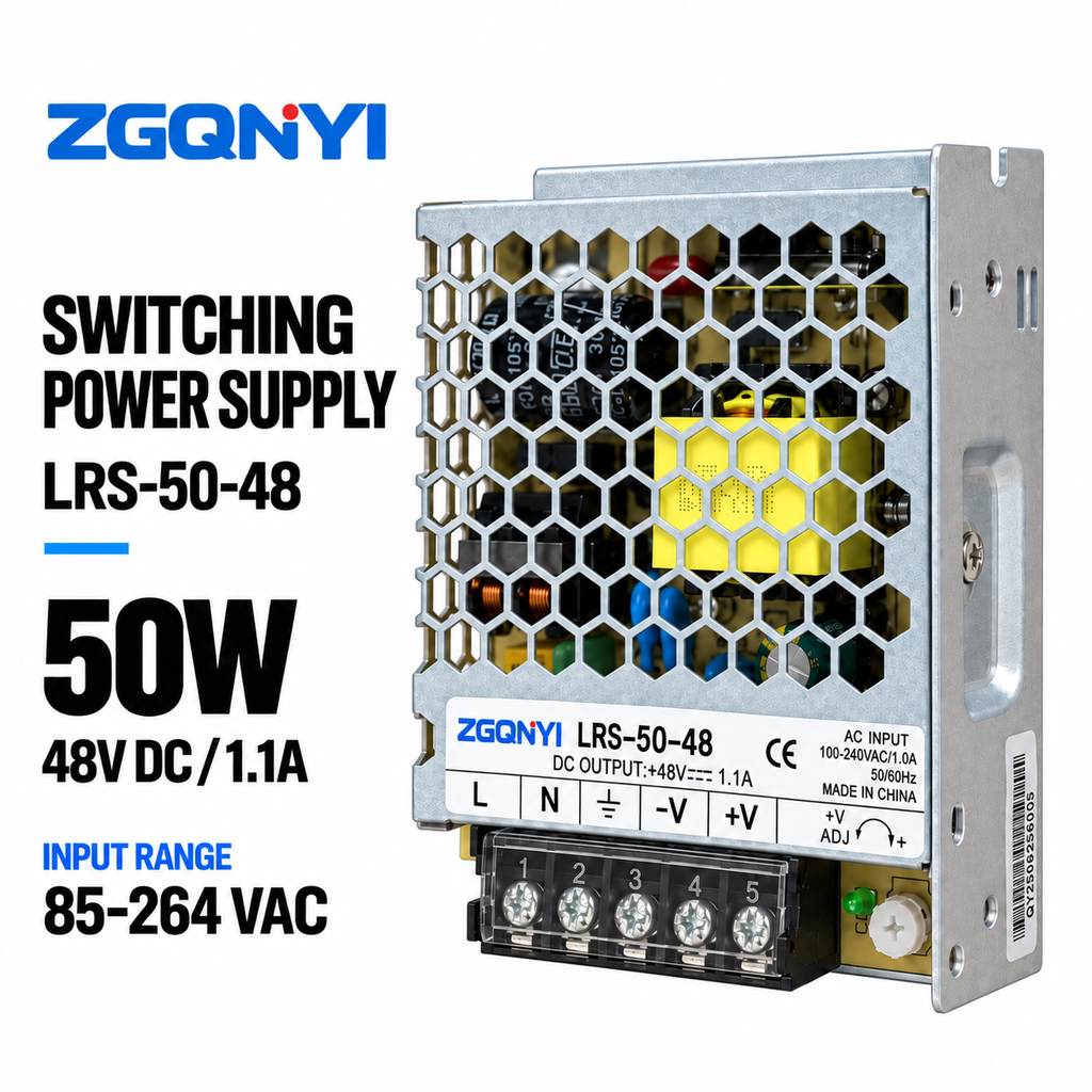
ZGQNYI LRS-50-48 48V Compact Enclosed Switching Power Supply
- Single Output 48VDC SMPS
- Telecom Repeaters & Network Nodes
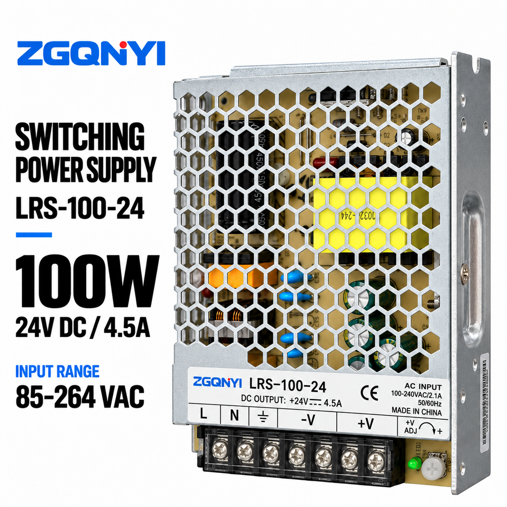
ZGQNYI LRS-100-24 100W 24V Switching Power Supply AC DC SMPS
- High Efficiency 24VDC 4.5A Rail
- PLC Cabinets & Industrial Automation
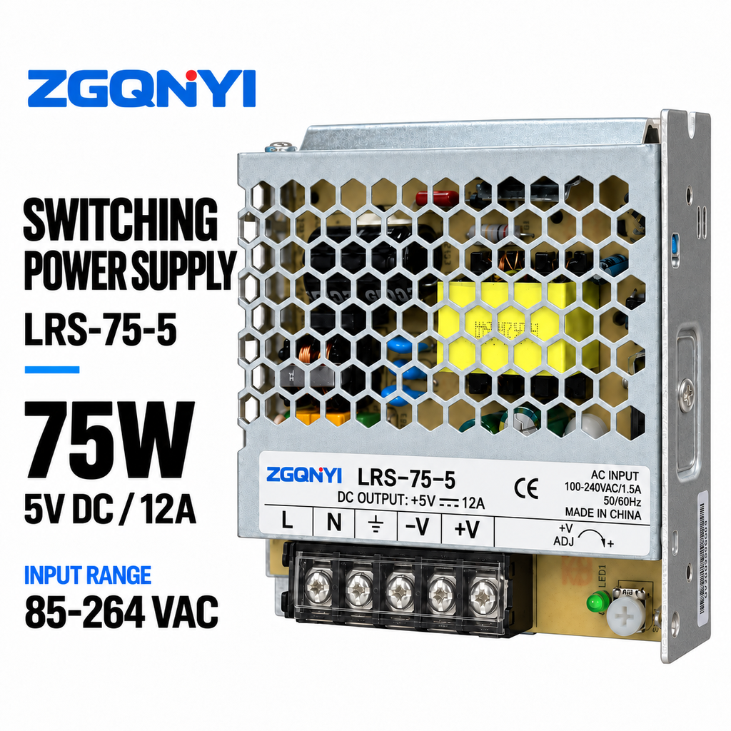
ZGQNYI LRS-75-5 5VDC Constant Voltage LED Driver SMPS
- Low Ripple 5VDC 14A Driver
- High-Density LED Matrix Displays
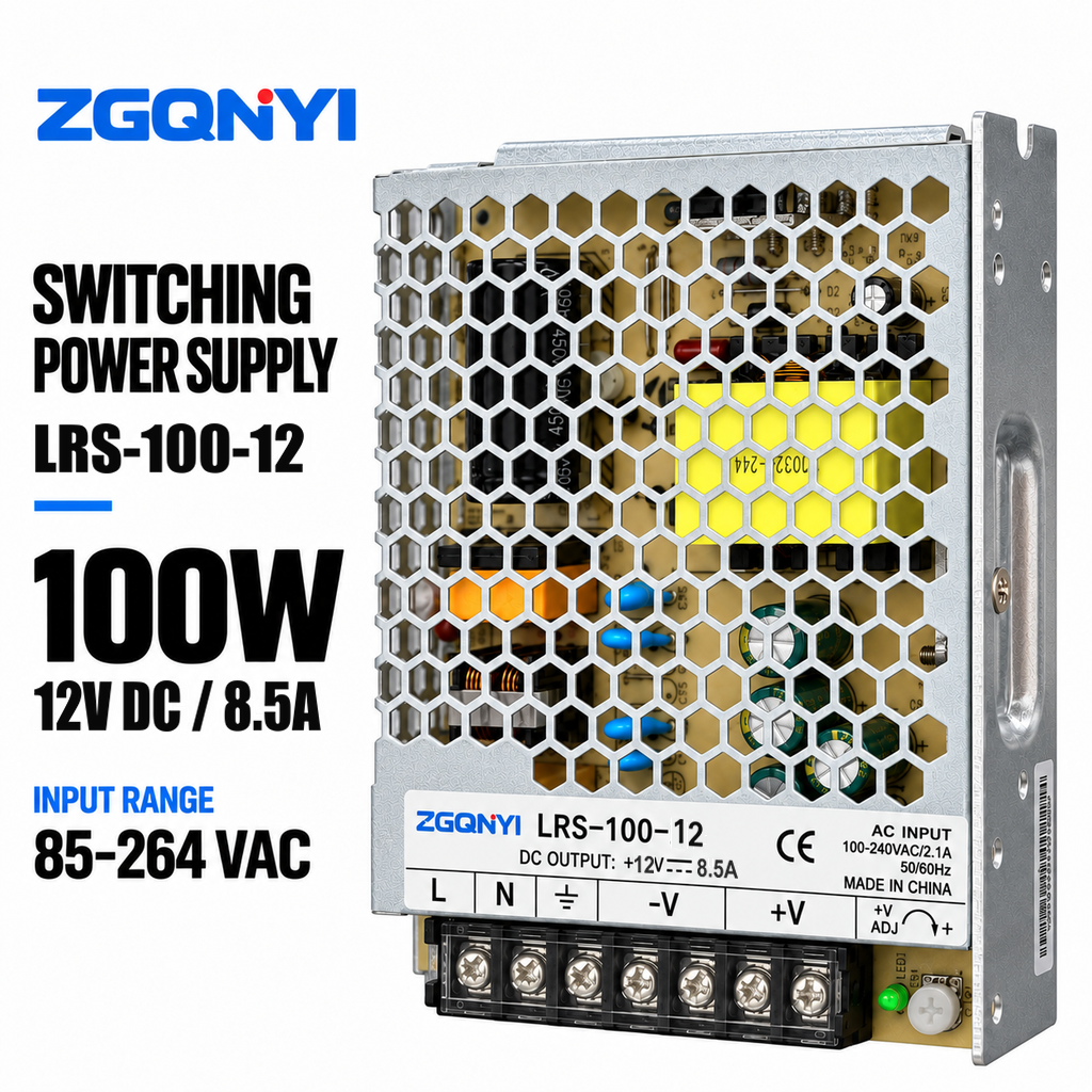
ZGQNYI LRS-100-12 100W 12V Industrial Power Supply AC/DC
- Low Thermal Dissipation 12V 8.5A
- CNC Panels & Motion Controller Units
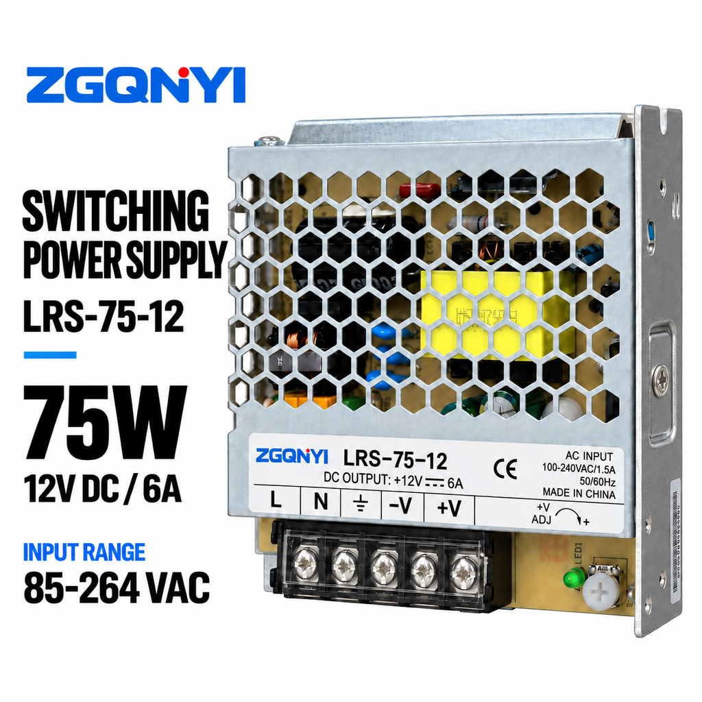
ZGQNYI Industrial 12VDC Power Supply LRS-75-12 Single Output
- Ultra-Low Standby Power < 0.3W
- Intercom & Continuous CCTV Nodes
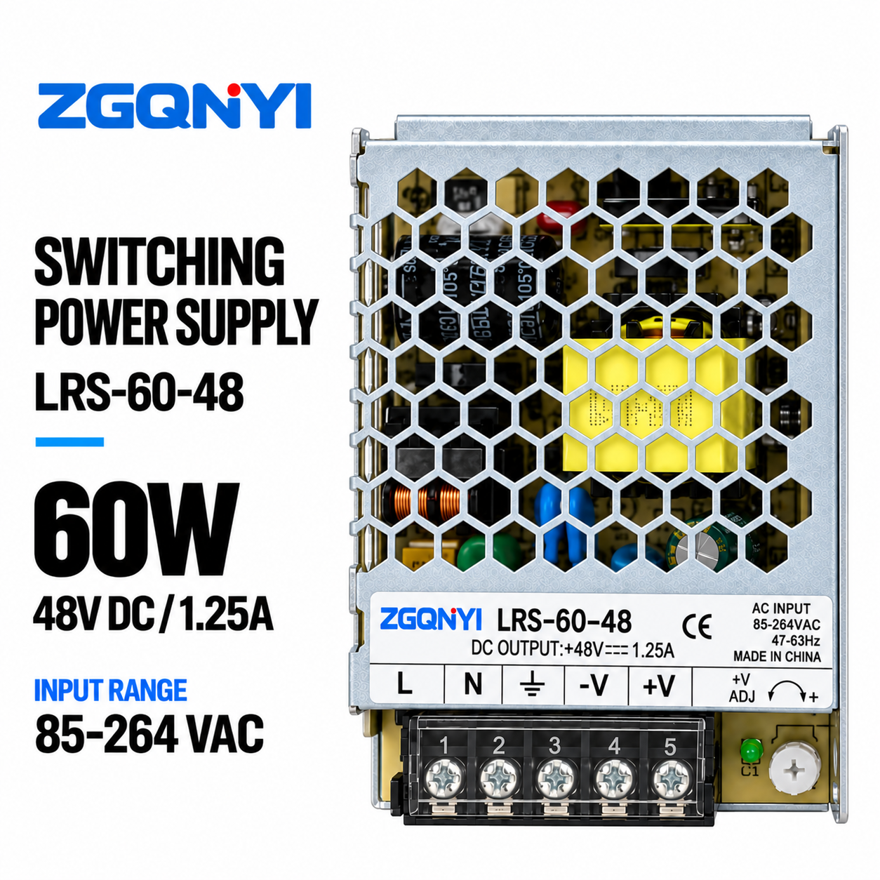
ZGQNYI Industrial 48V Power Supply LRS-60-48 Enclosed SMPS
- 300VAC Surge Input Withstand (5s)
- Building Controls & Distributed Sensors
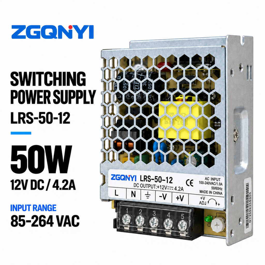
ZGQNYI LRS-50-12 12V DC LED Driver Switching Power Supply
- Constant Voltage 12V 4.2A SMPS
- Cabinet Architectural Illumination
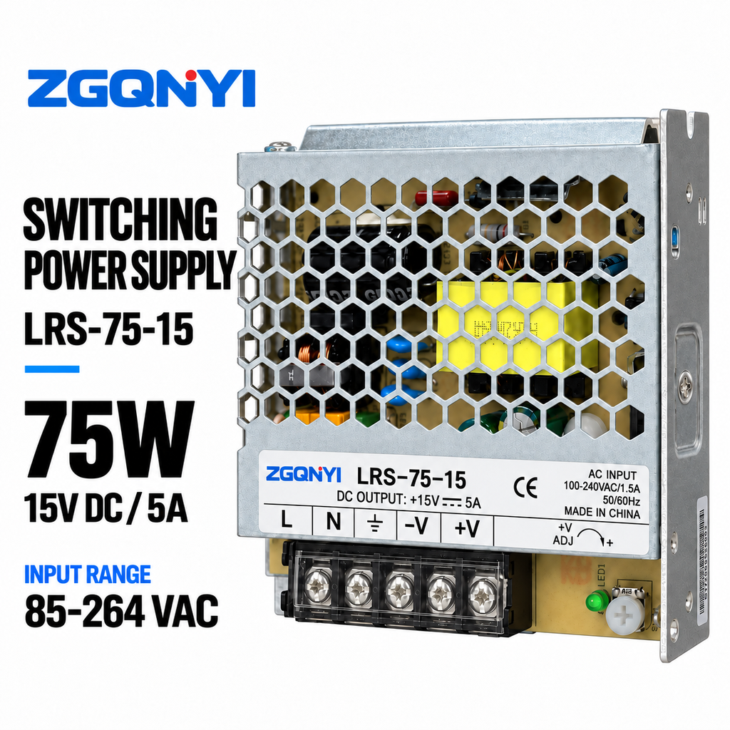
ZGQNYI LRS-75-15 Industrial Switching PSU 15V Enclosed SMPS
- Dedicated 15V 5A Sub-System Bus
- Machine Controllers & Electrical Panels
Active vs. Passive PFC Topologies: Why Power Quality Matters
Harmonic suppression, thermal optimization, and energy compliance standards dictate the next decade of power converter deployment across smart factories and infrastructure.
In modern industrial power electronics, Power Factor Correction (PFC) is no longer merely an optional efficiency add-on—it is a compulsory design mandate regulated by international electromagnetic compatibility and harmonic mitigation frameworks such as IEC/EN 61000-3-2 (Harmonic Current Emissions for equipment input current ≤ 16A per phase) and IEEE 519. Non-linear reactive loads created by conventional rectifier-capacitor input stages produce pulsating current waveforms rich in odd-order harmonics (3rd, 5th, 7th, 9th, and 11th orders). This non-sinusoidal current distortion not only degrades grid stability by elevating Total Harmonic Distortion (THD) above 75%, but it also leads to severe neutral conductor overheating, premature failure of upstream distribution transformers, and substantial power factor penalties from regional electric utility suppliers.
Engineering Insight: Defining Power Factor in Modern SMPS
Power Factor (PF) is the mathematical ratio of True Real Power (P, measured in Watts) absorbed by the load to Apparent Power (S, measured in Volt-Amperes) delivered by the grid: PF = P / S = (I1_rms / I_rms) × cos(θ) = K_distortion × K_displacement. In standard switched-mode conversion without active correction, even if voltage and fundamental current are in phase (displacement factor cos(θ) ≈ 1), the distortion factor (K_distortion) drops the overall PF down to 0.55–0.65, meaning up to 45% of apparent power is wasted as uncompensated circulating reactive power.
As an internationally accredited OEM/ODM power supply manufacturer, Wenzhou Nuvros Electric Co., Ltd. integrates multi-stage Active PFC (APFC) converter topologies across its standard and custom power platforms ranging from compact enclosed modules to ultra-high-power 1kW–18kW programmable systems. Active PFC circuits utilize closed-loop pulse-width modulated (PWM) boost converters operating at continuous conduction mode (CCM) or critical conduction mode (CrCM). By forcing the line current to dynamically track the sinusoidal profile of the input AC line voltage across a universal voltage range (85VAC to 264VAC, 47–63Hz), our active PFC stages push the steady-state Power Factor beyond 0.98 at rated load while driving THD down to under 5%.
| Architecture Criterion | Passive PFC (Inductive/Capacitive) | Continuous Conduction Mode (CCM) Active PFC | Interleaved / Bridgeless Totem-Pole PFC |
|---|---|---|---|
| Typical Power Factor (PF) | 0.70 – 0.80 | 0.96 – 0.99 | 0.992 – 0.998 |
| Total Harmonic Distortion (THD) | 35% – 65% | < 8% (Down to 5% at full load) | < 3% across wide dynamic loads |
| Input Voltage Operability | Narrow range (Requires manual 115V/230V switch) | Universal 85 – 264VAC (Full range auto-ranging) | Wide-spectrum 85 – 305VAC (Industrial 277VAC ready) |
| Chassis Volume & Weight | Bulky, heavy 50/60Hz laminated core chokes | Compact high-frequency magnetic toroids | Ultra-compact flat planar inductors (GaN/SiC) |
| Regulatory Compliance | Marginal IEC 61000-3-2 Class D pass | Full compliance with IEC 61000-3-2 Class A, B, C, D | Exceeds 80 PLUS Titanium & ErP Lot 6 Tier 2 |
| Primary B2B Use Cases | Cost-sensitive entry machinery, basic fans | Industrial automation, PLC, medical, CNC consoles | Data center server racks, telecom 5G, electrolysis, EV |
Technological & Development Trends in PFC Power Supplies
Next-generation power delivery demands wide-bandgap semiconductors, digital signal controller firmware, bidirectional energy transfer, and ultra-high volumetric densities.
1. Wide-Bandgap GaN & SiC Semiconductors
Gallium Nitride (GaN) HEMTs and Silicon Carbide (SiC) Schottky diodes replace legacy silicon MOSFETs. GaN allows PFC switching frequencies to leap from 65kHz up to 500kHz+, drastically reducing inductor footprints while slashing reverse recovery charge losses (Qrr ≈ 0) in bridgeless totem-pole topologies.
2. Digital Control Loop & DSP Integration
Transitioning from analog ICs (like UCC28019) to high-speed Digital Signal Processors (DSP) allows non-linear adaptive control algorithms, dynamic dead-time trimming, phase-shedding at light loads, and real-time frequency dithering to circumvent conducted EMI emissions without oversized passive filters.
3. Extreme Volumetric Power Density (W/in³)
Standard industrial power brick profiles are evolving toward >30W/in³ densities. High-conductivity thermal potting resins, double-sided SMD reflow boards, direct bonded copper (DBC) substrates, and integrated magnetics enable 3000W output in compact 1U rack-mountable chassis heights.
4. Fieldbus Telemetry & PMBus/RS485
Smart factory IoT frameworks require intelligent telemetry. Modern PFC supplies incorporate optoisolated RS485 (Modbus RTU), CANopen, or I2C/PMBus protocols to report live input voltage, line current, active power, internal heat-sink temperatures, and predictive capacitor health status.
Future Procurement Trends in the Global PFC Power Supply Market
Strategic sourcing managers are adapting to stricter carbon border adjustments, total cost of ownership (TCO) analyses, and supply chain modularity.
Strict Harmonic Regulations & ErP Eco-Design
European Union EcoDesign directives (including ErP Lot 9 for enterprise servers and data storage) now enforce minimum active efficiency thresholds (>94% at 50% load) and strict idle mode wattage (<0.5W). OEMs unable to deliver verified active PFC test certificates face border customs bans and severe carbon tax surcharges across EU and North American jurisdictions.
Total Cost of Ownership (TCO) Prioritization
Procurement teams are shifting away from cheap, low-PF power units. For continuous 24/7 process loads (such as electroplating baths, water treatment electrolysis, and server farms), a 3% efficiency improvement combined with a 0.99 PF saves thousands of kilowatt-hours per unit annually, amortizing the initial capital cost difference within 6 to 9 months of active operation.
OEM/ODM Customization over Off-the-Shelf
To differentiate their machine products, machine tool builders and robotics developers demand tailored form factors, specialized mounting brackets, dual/triple auxiliary voltage taps, conformal PCB coatings (MIL-I-46058C) against corrosive plant atmospheres, and branded private labeling with pre-certified regional safety markings.
Your Verified OEM/ODM Power Supply Partner in China
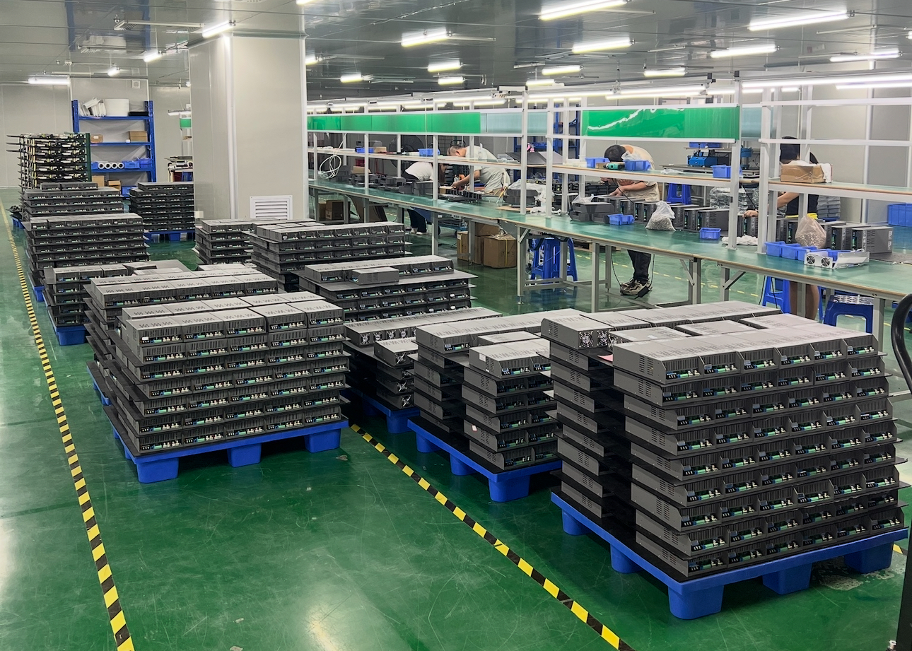
Situated in Beibaixiang Town, Wenzhou—the premier hub of China's electrical apparatus industry—Wenzhou Nuvros Electric Co., Ltd. stands as an engineering-driven power supply manufacturing enterprise with over 18 years of specialized R&D experience. Spanning more than 10,000 square meters of production space across our headquarters and manufacturing divisions, we offer direct factory integration from circuit topology prototyping to automated mass assembly.
Our facilities boast fully automated SMT pick-and-place lines, lead-free selective wave soldering, automated optical inspection (AOI), computerized in-circuit testing (ICT), and multi-bay 100% full-load high-temperature burn-in chambers. Every single production batch undergoes rigid dielectric withstand testing (Hipot 3.0kVAC Input-to-Output), insulation resistance screening, and rigorous thermal imaging validation.
- 500,000 Pcs Monthly Production Capacity
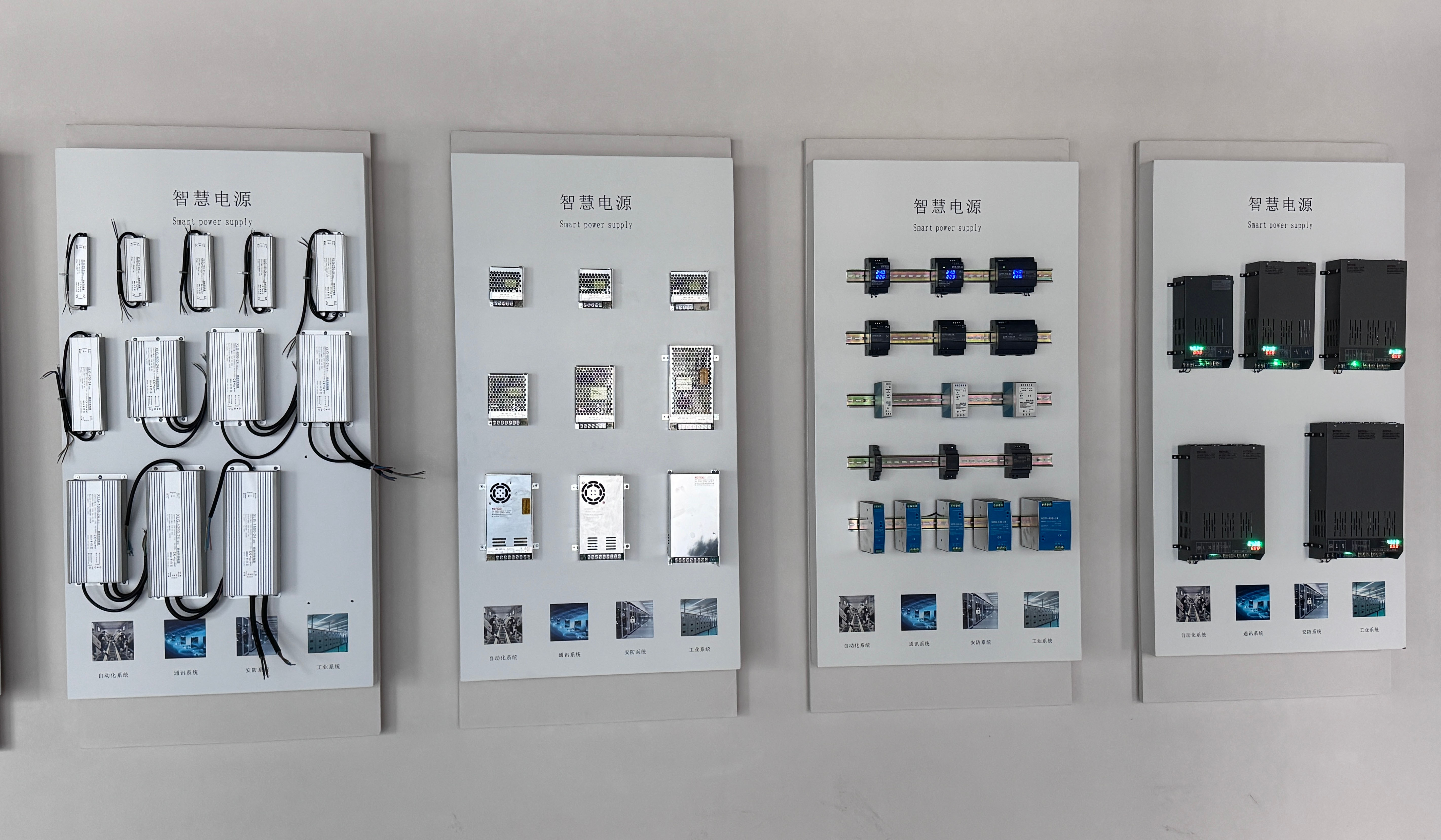
- 1,000+ Standard SKUs (DIN Rail, Enclosed, High Power)
- CE & RoHS Listed Certified Product Models
- Complete In-House OEM/ODM Tooling & Firmware Design
- 1-Hour Average Engineering Response Rate
- Multi-Lingual Export Documentation & DDP Terms

Frequently Asked Questions: PFC Power Supply Sourcing
Critical engineering considerations, testing standards, customization parameters, and supply chain trade terms answered by our senior power architects.
What is the core distinction between Active PFC and Passive PFC in industrial SMPS?
Passive PFC uses heavy line-frequency (50/60 Hz) chokes and fixed capacitor networks to broaden current conduction angles. It yields a mediocre PF of 0.70–0.80, functions only in narrow input voltage bands (e.g., 230VAC only), and adds significant physical weight. In contrast, Active PFC utilizes an active semiconductor boost switch (MOSFET/GaN), high-frequency magnetics, and closed-loop feedback controllers to dynamically sculpt line current into an exact replica of the AC voltage wave. This achieves a PF > 0.98, limits THD under 5%, and provides flawless universal auto-ranging input from 85VAC to 264VAC without mechanical selector switches.
When is active PFC legally mandated under international compliance frameworks?
Under EN 61000-3-2, all electrical and electronic equipment with active power consumption exceeding 75 Watts distributed in the European Union must comply with harmonic emission limits. For lighting equipment (Class C), strict harmonic requirements apply starting from just 25W (and even 5W in certain LED drivers under newer iterations). Active PFC is essentially compulsory to meet Class C and Class D harmonic brackets, ensuring equipment clears CE, UKCA, and CCC regulatory audits.
How do you calculate thermal derating when installing power supplies inside sealed control cabinets?
Most industrial switching power supplies deliver 100% rated output up to +45°C or +50°C ambient temperature. Beyond this threshold, thermal derating applies at a rate of 2.0% to 2.5% rated power per °C elevation, operating up to +70°C. When sizing a unit for sealed NEMA 4X / IP66 enclosures where internal heat buildup cannot escape via forced convection, calculate total thermal load using: P_loss = P_output × (1 - Efficiency) / Efficiency. Always maintain a minimum 20% to 30% continuous power reserve margin to safeguard electrolytic capacitor electrolyte lifespan (Arrhenius equation rule: every 10°C core temperature rise halves capacitor MTBF).
What parameters can be customized under your OEM and ODM programs?
As a bespoke factory manufacturer, Nuvros provides complete ODM development including: non-standard DC output rails (e.g., 36V, 60V, 72V, 110V, 220VDC), constant voltage / constant current (CV/CC) limit programming, high peak-current burst capabilities for inductive motor inrush (up to 200% for 3 seconds), specialized conformal anti-fungal coatings for humid tropical deployments, unique enclosure dimensions (ultra-slim 1U or DIN rail forms), integrated digital V/A displays, and communication buses (isolated RS485 Modbus RTU, CAN, PMBus). Private labeling, branded metal stamping, and customized master carton packaging are fully supported.
What are your minimum order quantities (MOQ), prototyping lead times, and trade terms?
For standard catalog models, samples can be dispatched from 1 piece with stock availability within 24 to 72 hours. For customized OEM/ODM projects, engineering prototype verification typically requires 15 to 25 business days depending on tooling and magnetic winding requirements. Bulk mass production lead times generally range between 3 to 4 weeks. We support global trade terms including FOB Ningbo/Shanghai, CIF, CFR, EXW, FCA, and door-to-door DDP (Delivered Duty Paid). Multi-currency transactions are accepted in USD, EUR, and CNY via T/T, L/C, PayPal, or Escrow.
Why is hold-up time crucial in industrial PLC and telemetry applications?
Hold-up time refers to the duration (typically measured in milliseconds, ≥ 16ms or ≥ 20ms at full load) during which the power supply continues to maintain regulated DC output voltage within spec after complete loss of input AC line voltage. In automated manufacturing lines, this critical window provides PLCs, IPCs, and motion controllers sufficient time to write register states into non-volatile memory, execute graceful robotic brake interlocks, or switch over to backup uninterruptible power supplies (UPS) without unpredictable data corruption or machine crashes.